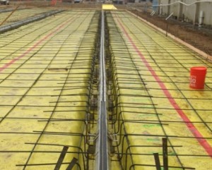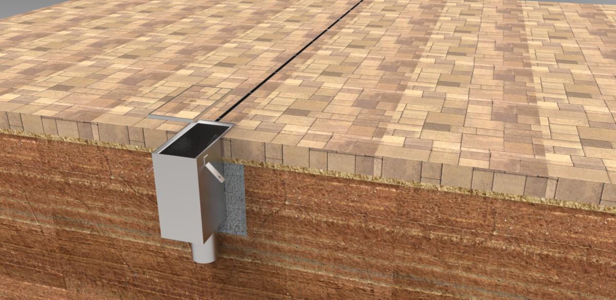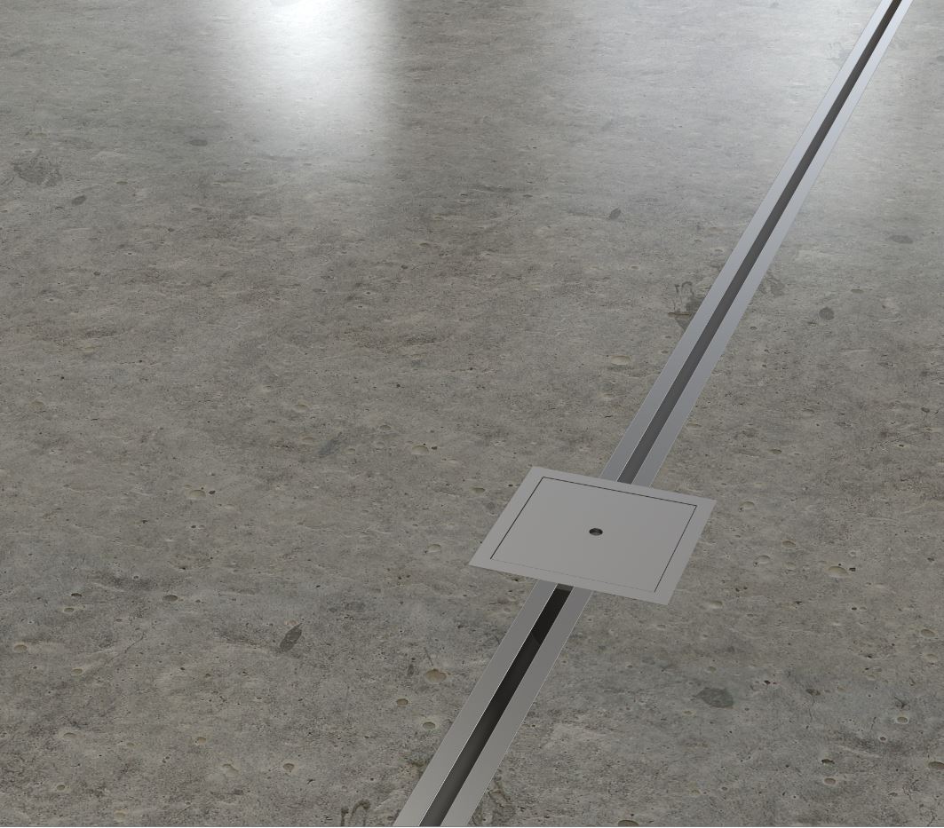
- Slot Drain Installation Detail
- Bielbet Slot Drain Installation
- Gatic Slot Drain Installation
- Slot Drain Install
In addition to the standard fixed slot height style, Duraslot drains are available with a variable height slot to permit slope in the pipe invert when grade is level. The standard change in slot height is 5/8” (16 mm) per 10’ (3 m) length (H 2. Slot Drain Installation. Slot Drain is a one-piece, built-in, sloped drainage system with a linear slot in the floor surface at a constant elevation. The drain itself is mounted in the floor assembly and integrated with the floor during the concrete pour.

NEW CONSTRUCTION

Slot Drain® is pre-sloped and fully assembled. It is easy to install, reducing labour costs and minimizing chances of error.
Drain sections arrive fully assembled and ready to install — no grating to screw on, no anchors or drains to weld, simply bolt the drain ends together, then pour your floor.
It takes two people approximately 20 to 30 minutes to install one 15 foot section.
1) Excavate a trench allowing for room underneath and on both sides of Slot Drain®. There should be a minimum of 6″ of concrete surrounding the drain.
2) It is recommended to pre-pour a concrete pad underneath the Slot Drain® pit so it can be properly secured. If no pad is poured, peg the sump pit down (using the flat bar mounting brackets bolted to the sides of the sump and wooden stakes) before Slot Drain® is connected.
3) Install all Slot Drain® pits and piping, making sure that the Slot Drain® pit walls are reinforced to prevent sidewall bowing.
4) Bolt the last (deepest) section of Slot Drain® to the Slot Drain® pit. If a Slot Drain® pit is not being used, start at the deepest section. Bolt all remaining sections of Slot Drain® together using the numbered flanges as a guide. For example, if you have a section 102, a section 203, a section 304 and a Slot Drain® pit. First, bolt flange 4 of section 304 to the Slot Drain® pit side marked 4. Next, bolt flange 3 of section 304 to flange 3 of section 203. Finally, bolt flange 2 of section 203 to flange 2 of section 102. Use a continuous bead of silicone sealant between all bolted sections.
5) Use wooden stakes to set the desired elevation of drain sections. Secure drain sections to the stakes with the mounting holes provided on the levelling brackets.
6) Once Slot Drain® is secured and the appropriate elevation is achieved, for structural support, tie the rebar from the floor grid into the rebar/levelling bars on the drain assembly. Cover the opening with the duct tape, or insert Styrofoam if needed.
7) To ensure that Slot Drain® will not float, it is recommended that the concrete be poured in two stages. Once adequate time for the first concrete pour to set has elapsed, the floor slab can be completed. The use of a pencil vibrator is strongly recommended to make sure that the concrete has completely surrounded Slot Drain®, leaving no bubbles or voids.
8) Once the concrete slab is firm, first remove the tape or Styrofoam from the slot and then break out all metal tabs to ensure a continuous open slot. Using the paddle, clean out the Slot Drain®.
RETROFIT
Slot Drain Installation Detail
Slot Drain® Systems arrives at the site in fully assembled sections and is ready to be installed.
1) Layout and mark drain location on existing slab.
2) Cut 24″ wide trench in existing slab.
3) Excavate the trench allowing for room underneath and on both sides of Slot Drain®.. There should be a minimum of 6″ of concrete surrounding the drain.
4) Drill and dowel into the sides of the existing cut slab. Approximately 16″– 24″ on both sides.
Bielbet Slot Drain Installation

5) It is recommended to pre-pour a concrete pad underneath the Slot Drain® pit so it can be properly secured. If no pad is poured, peg the sump pit down (using the flat bar mounting brackets bolted to the sides of the sump and wooden stakes) before Slot Drain® is connected.
6) Install all Slot Drain® pits and piping, making sure that the Slot Drain® pit walls are reinforced to prevent sidewall bowing.
7) Bolt the last (deepest) section of Slot Drain® to the Slot Drain® pit. If a Slot Drain® pit is not being used, start at the deepest section. Bolt all remaining sections of Slot Drain® together using the numbered flanges as a guide. For example, if you have a section 102, a section 203, a section 304 and a Slot Drain® pit.
First, bolt flange 4 of section 304 to the Slot Drain® pit side marked 4. Next, bolt flange 3 of section 304 to flange 3 of section 203. Finally, bolt flange 2 of section 203 to flange 2 of section 102. Use a continuous bead of silicone sealant between all bolted sections.
8) Use wooden stakes to set the desired elevation of drain sections. Secure drain sections to the stakes with the mounting holes provided on the levelling brackets.
9) Once Slot Drain® is secured and the appropriate elevation is achieved, for structural support, tie the rebar from the dowels and floor grid into the rebar/levelling bars on the drain assembly. Cover the opening with the duct tape, or insert Styrofoam if needed.
Gatic Slot Drain Installation
10) To ensure that Slot Drain® will not float, it is recommended that the concrete be poured in two stages. Once adequate time for the first concrete pour to set has elapsed, the floor slab can be completed. The use of a pencil vibrator is strongly recommended to make sure that the concrete has completely surrounded Slot Drain®., leaving no bubbles or voids.

Slot Drain Install
11) Once the concrete slab is firm, first remove the tape or Styrofoam from the slot and then break out all metal tabs to ensure a continuous open slot. Using the paddle, clean out the Slot Drain®.